


CAD/CAM systems for manufacturing companies
AVADA MEDIA develops CAD systems for manufacturing companies — from highly specialized engineering tools to full-fledged platforms integrated with configurators, CRM/ERP, and production lines.
We cover the entire product cycle, from digital design to actual production:
- develop CAD software for parametric design of products;
- create 2D and 3D configurators for clients and managers;
- develop and implement CPQ (Configure-Price-Quote) systems with automatic cost calculation;
- automate the generation of drawings, specifications and production documentation;
- integrate solutions with CRM/ERP systems;
- connect the system with production software, CNC machines and processing lines.
As a result, you receive not a set of disparate tools, but a unified digital system for working with the product.
Your production begins to operate smoothly: quickly, accurately, and without dependence on people — more orders, lower costs and stable growth.
What is a CAD/CAD system?
A CAD system is used by an engineer or technologist to design a product and create an accurate 2D or 3D model that reflects the actual design:
- geometry (shape, dimensions);
- composition of the product (parts, units);
- materials.
The model serves as a single digital foundation on which all subsequent processes are carried out:
- calculations;
- generation of documentation;
- preparation of production.
Using the model in the configurator
The finished CAD model can be used in a 2D or 3D configurator on the company's website, which is used by clients, dealers, partners, and managers.
Key value: An engineer designs and configures a model in a CAD system once, and then uses it repeatedly:
- in sales - through the configurator;
- in calculations - to form costs and specifications;
- in production - to prepare data and start production.
What does a CAD/CAD system consist of?
A CAD system is not a single module, but a set of interconnected components that together provide a complete product development cycle: from design to production.
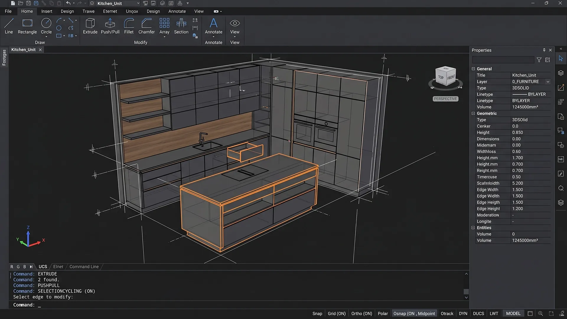
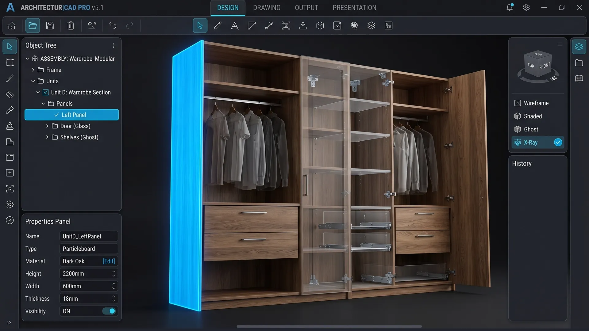
1. Geometric core (modeling)
This is the base layer, which is responsible for constructing the very shape of the product.
What is being implemented:
- construction of 2D and 3D geometry;
- working with bodies, surfaces and contours;
- modeling operations (extrusion, cuts, merging);
- formation of the product structure.
Result: an accurate digital model is created that corresponds to the actual structure.
2. Parametric engine (product logic)
The key component that makes the model manageable.
What is being implemented:
- system of parameters (dimensions, materials, options);
- dependencies between elements;
- rules and restrictions.
Example: changing one parameter automatically recalculates the entire structure.
Result: the product is controlled via parameters, not manually.
3. Assembly module (product structure)
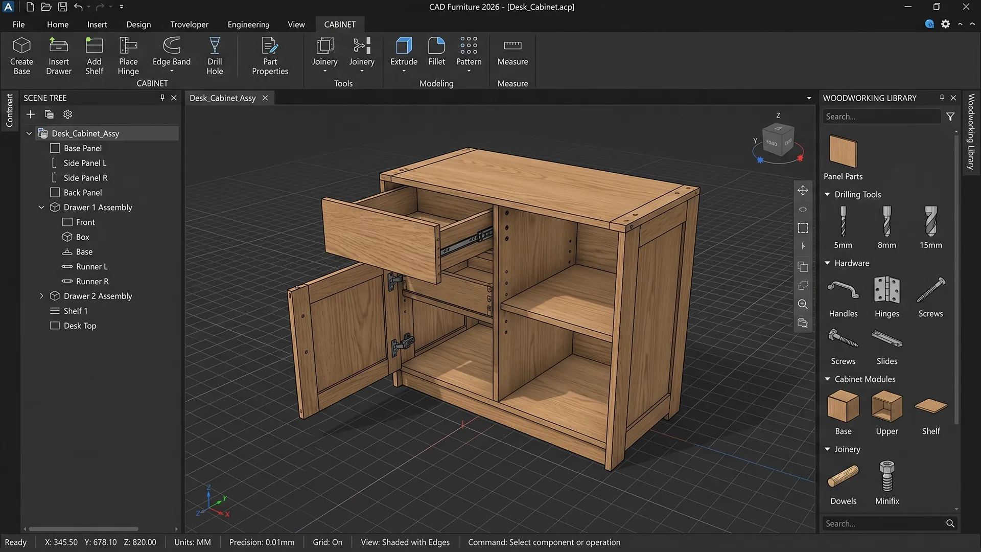
Works with composite products.
What it does:
- combines parts into an assembly;
- manages relationships between elements;
- takes into account the location and interaction of parts.
Result: correct structure of the product and control of its integrity.
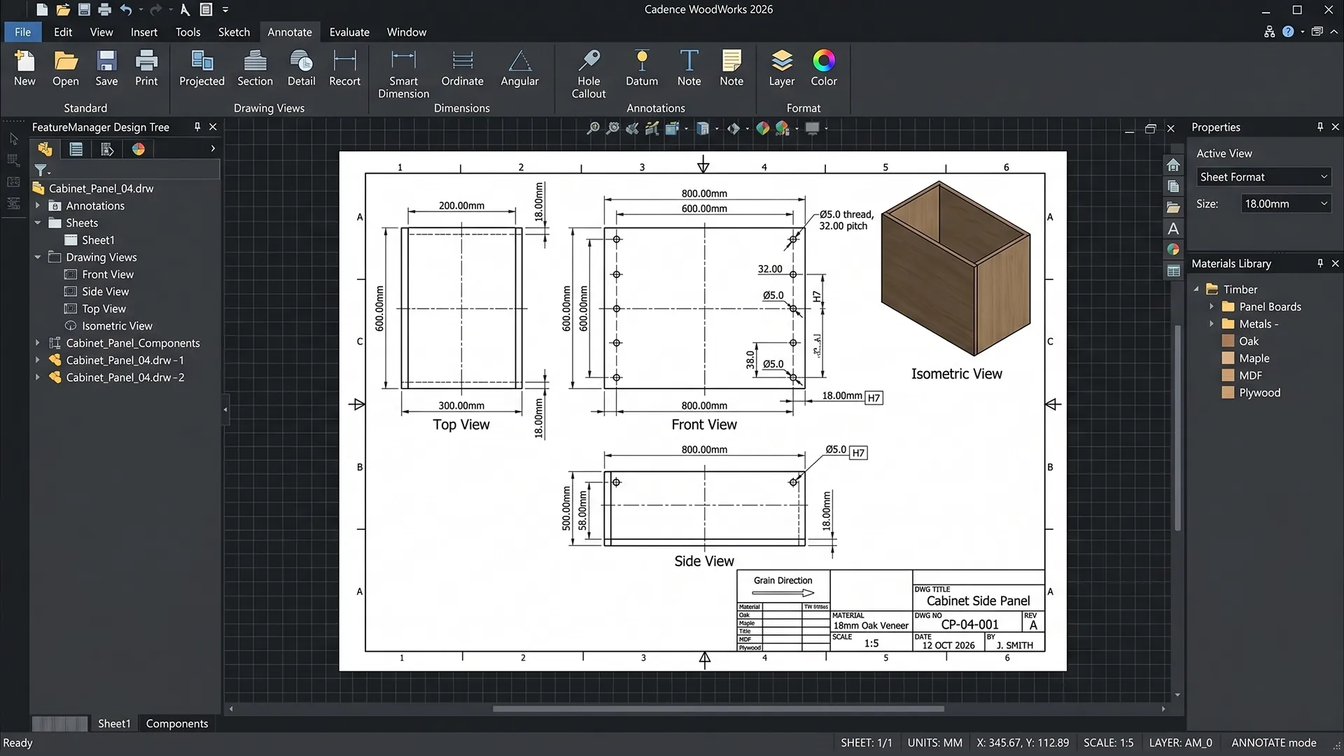
4. Drawing generation module
Responsible for preparing documentation.
What is being formed:
- working drawings;
- dimensions and tolerances;
- sections and views;
- assembly diagrams.
Result: a complete set of documentation corresponding to the model.
5. Bill of Materials (BOM)
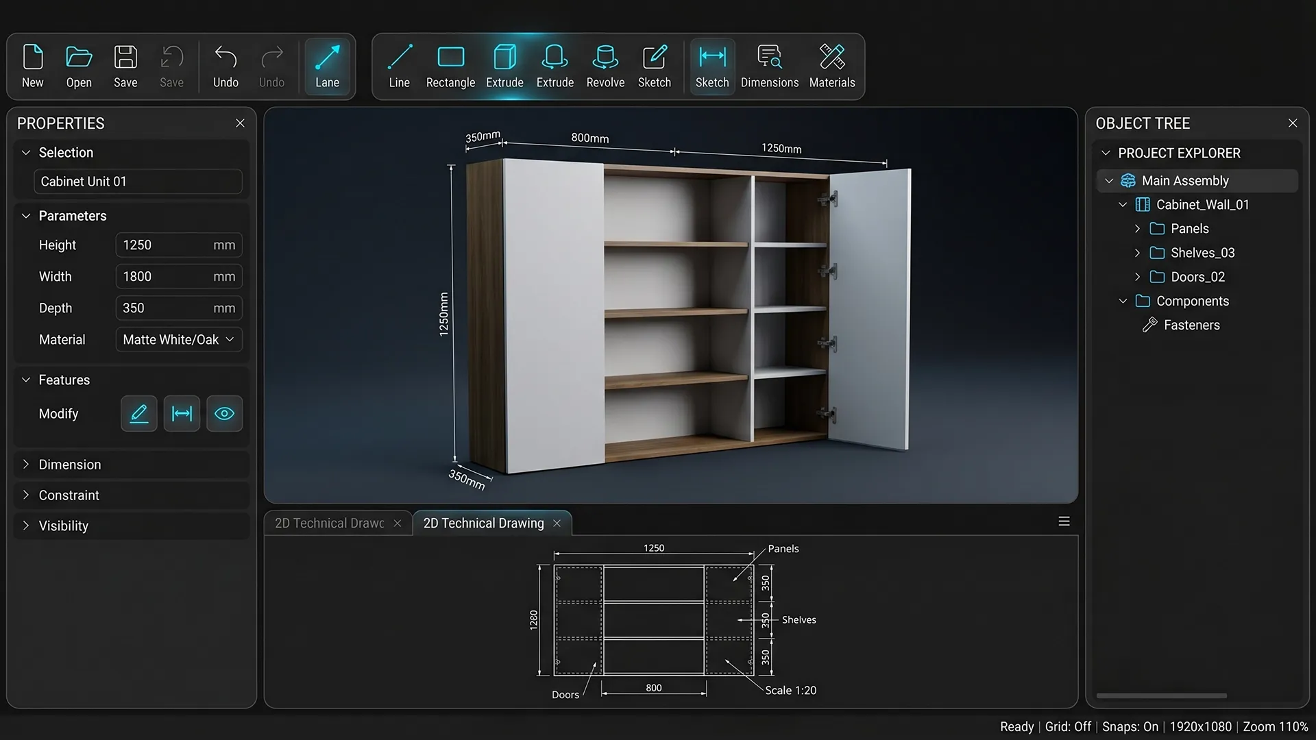
Links the model to the economics of the product.
What it does:
- generates a list of parts and materials;
- calculates quantity;
- participates in the cost calculation.
Result: precise specification and basis for price calculation.
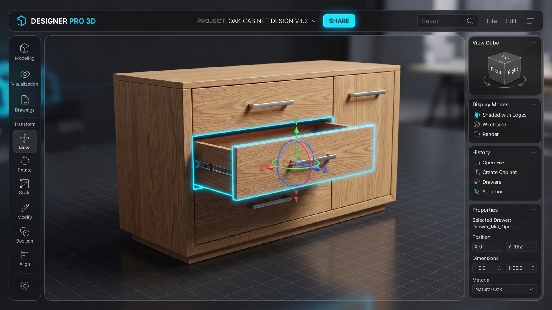
6. Interfaces and display
Responsible for user interaction with the system.
What it includes:
- 2D/3D visualization;
- editing interfaces;
- real-time model display.
Result: clear and intuitive product control.
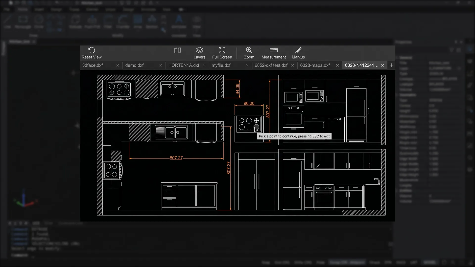
7. Integration with production and external systems
This module connects the CAD system with real business processes—from order placement to production launch.
What is being implemented:
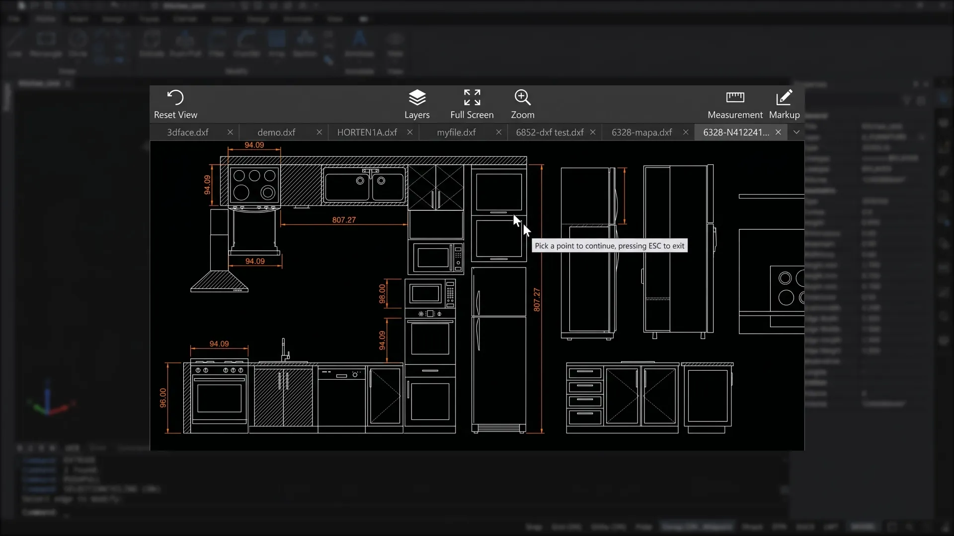
- export to production formats (DXF, STEP, etc.);
- preparation of data for CNC and generation of processing files;
- data transfer to production systems and equipment;
- integration with CRM/ERP;
- integration with 2D/3D configurators (the CAD model is prepared in web formats for use in configurators: for 3D: glTF / GLB (standard for WebGL) or for 2D: SVG. The model is optimized, broken down into elements and linked to parameters for interactive work;
- or vice versa - the configuration collected by the client or manager in the configurator is transferred to the CAD system, where a model, specification, and production files are automatically generated on its basis.
Result: data from the CAD system is directly used in sales, calculations, and production, forming a single digital chain without gaps between stages.
8. Data warehouse
Responsible for information management.
What is stored:
- product models;
- parameters;
- versions;
- templates.
Result: data control and model reuse.
When and what kind of business needs its own CAD system
An in-house CAD system becomes essential when orders are already flooding in, but key processes are still performed manually. At this point, the business begins to lose speed and control.
Typically it looks like this:
- each order requires the participation of an engineer;
- calculations are performed manually;
- Preparing a proposal takes time;
- errors occur when transferring data to production;
- Sales, accounting and production operate in isolation.
Key message: increasing orders requires expanding the team, not speeding up processes.
This situation is typical for businesses where the product is assembled each time according to the client's parameters, dimensions, and configurations.
Most often, these are companies that produce:
- kitchens, wardrobes, closet systems;
- entrance and interior doors with configurations;
- windows, stained glass, facade systems;
- stairs, canopies, metal structures;
- trade equipment, stands, display cases;
- any products with variable sizes, materials and configurations.


How this might work in practice
Let's look at an example of use using a manufacturing company that produces kitchens.
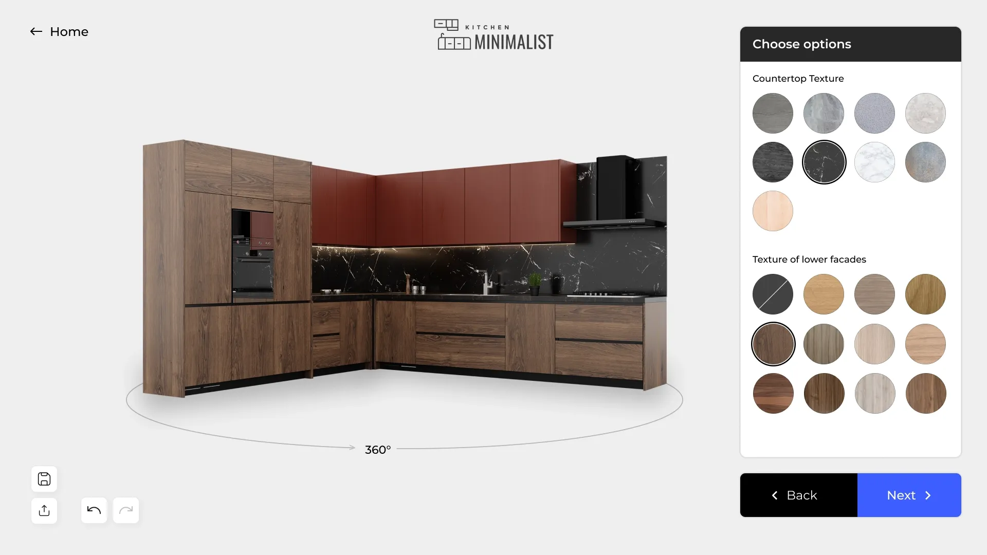
The client visits the website and opens the kitchen configurator. The company hosts a 2D or 3D configurator on the website, allowing the client to assemble their desired kitchen. They select the kitchen shape, room dimensions, module configuration, front material, color, countertop, hardware, and other parameters.
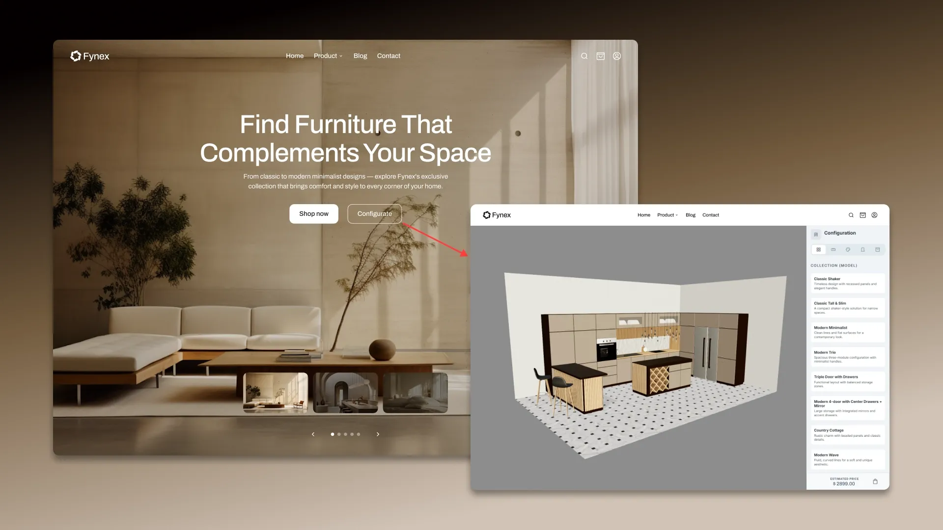
The system assembles the product in real time based on the selected parameters. As you configure the kitchen, the configurator instantly displays how it will look. Simultaneously, the system recalculates the section sizes, the number of modules, and the product composition, verifying that the selected configuration complies with the specified logic and production constraints.
The client immediately receives an up-to-date price. The system updates the price after each change to the parameters. The price is calculated based on dimensions, materials, fittings, configuration complexity, and other rules pre-programmed into the system.
The completed configuration is transferred to the CAD system. Once the client completes the customization, the entire assembled configuration is transferred to the CAD system. At this stage, the parameters from the configurator become the basis for a precise digital model of the product.

The CAD system automatically generates the kitchen design. Based on the received data, the system assembles a complete kitchen model: it determines the composition of modules, the dimensions of parts, materials, assemblies, and the connections between elements. This is no longer just a visualization, but a fully-fledged engineering model suitable for calculations and production.
A product specification is generated. The system automatically creates a BOM: a list of cabinets, fronts, shelves, countertops, fittings, fasteners, and other components with precise quantities and parameters. This BOM can be used for cost calculations, procurement, and production.
Drawings and production files are generated. After the model is assembled, the CAD system creates a set of documents and files for production: drawings, cutting plans, DXF files, CNC data, and other necessary production information.
The order is recorded in the CRM or ERP. All order data — configuration, cost, specifications, lead time, and production files — is transferred to the CRM/ERP. The manager, production, and other departments then work with the same configuration without re-entering data.
Production receives a completed order. The production department no longer receives disparate data from various sources (requests, correspondence, spreadsheets), but a fully prepared order with precise parameters, a parts list, and production files. This reduces start-up time and reduces the risk of errors.
The business gains a manageable process. As a result, a kitchen assembled by the client in the configurator is automatically converted into a ready-to-order production order. Sales, invoicing, and production operate as a single digital chain.
Ready-made vs. custom CAD systems
Systems like AutoCAD or SolidWorks solve the design problem, but do not create a unified process for working with an order.
In practice this means:
- complex adaptation to a specific product and business processes;
- there is no product logic and automatic dependencies;
- no connection with sales and configurator;
- each order requires manual work by an engineer;
- calculations and specifications are generated separately;
- The cost is calculated outside the system.
As a result, the process is fragmented, speed is dependent on people, and scaling is difficult.
Capabilities of a custom CAD system
A custom CAD system can be equipped with the following features:
Product design and management
- Automatic product assembly based on parameters: the system creates a design based on dimensions, materials and configuration;
- instant recalculation of the design: when changing parameters, all related elements are updated;
- 2D/3D model formation: an accurate model of the product is created;
- control of acceptable configurations: incorrect or non-producible options are excluded;
- fixing the structure and logic of the product: all rules, dependencies and restrictions are defined in the system.
Calculations and Economics
- generation of a bill of materials (BOM) : a list of parts, materials and their quantities is generated;
- automatic cost calculation: the price is calculated based on the parameters and logic of the product;
- dynamic pricing: the price changes in real time, taking into account the conditions;
- accounting of warehouse balances: available materials are used in calculations.
Production
- generation of production files: DXF and CNC data are generated;
- optimization of materials: cutting with minimal waste is calculated;
- manufacturability check: the possibility of production is checked;
- calculation of production lead times: complexity and workload are taken into account;
- distribution of orders to production: tasks are generated and transferred to work.
Sales and order processing
- product setup without the involvement of an engineer: the manager or client sets the parameters through the interface;
- use of the model in the configurator, CRM and production: a single model is applied at all stages;
- automatic generation of a commercial proposal: the commercial proposal is generated immediately after setup;
- product versioning: order options are saved and compared;
- templates and solution libraries: standard designs are used;
- Integration with the dealer network: a single tool with control over conditions.
Analytics and Scaling
- order and product analytics: popular configurations and margins are tracked;
- support for mass customization: processing a large flow of individual orders.
- generation of configurations based on text description: the system offers product options;
- intelligent design optimization: selection of solutions taking into account constraints and costs;
- recommendations on parameters and configuration: the system offers optimal settings;
- demand and order analysis: patterns and popular solutions are identified;
- AI assistant for customer service: helps select products and place orders.

Cost and timeframe for developing a CAD system
Each project is calculated individually, but the following are guidelines for stages and budget:
| Level | What's included | Deadlines | Price* |
|---|---|---|---|
| MVP / Pilot | Single-product parametric model, basic logic and dependencies, bill of materials (BOM) generation, basic costing, DXF export/basic manufacturing files | from 2 months | from €12 – 20k |
| Business Setup | Multiple product types, advanced parametric logic, drawing and documentation generation, CRM/configurator integration, pricing logic, CNC data preparation | 3-5 months | from €20 – 60k |
| Enterprise | Multi-product CAD (multiple product lines), complex product logic, integration with ERP, warehouse and production, automation of production processes, dealer accounts/configurators, AI functions | 6–9 months | from €60k+ |
*The price is given as a guide and depends on the specific task and the volume of the system.
What influences the cost?
The project cost depends on the complexity of the product's parametric logic, the level of production automation, the availability of a configurator (2D or 3D), the number and depth of integrations with CRM, ERP, and equipment, and the need to implement AI functions.
Development typically begins with an MVP — a logic test on a single product type — after which the system is scaled across the entire product line and supplemented with integrations and production automation.

Transfer production to the system
Stop relying on manual calculations and engineers' workloads. We'll create a CAD system that will automatically generate orders, calculations, and production data.
Submit a request – we’ll show you how this can work in your business.


FAQ
-
How much will current business processes need to be changed?
It's not necessary to "break" processes. Typically, the system first integrates into the current logic and then gradually optimizes it.
-
Who will support the system after launch? Is a separate IT department needed?
No, a separate department is not required. However, a responsible person within the company (product/technologist) who understands the product logic is needed. We train the team and provide them with the tools to independently work with parameters and rules.
-
Is it possible to initially implement only calculations and specifications without 3D?
Yes, and this is often a reasonable start. Many companies start with the "invisible" part— the BOM, the logic, and the cost and add visualization later.
-
What happens if a manager or client builds an “incorrect” configuration?
Nothing will happen — the system simply won't allow it. Constraints and rules are baked into the parametric model, making incorrect options physically impossible.
-
How can you tell if the system will truly pay for itself and not become an expensive toy?
There's a simple criterion: if an engineer is currently involved in every order, the system will pay for itself. You'll replace ongoing operational costs (people, time, errors) with a single, customized logic.
-
What's faster: hiring more engineers or implementing a CAD system?
Hiring is faster. Scaling is not. New engineers increase costs linearly, while the system allows for growth without a proportional increase in the team.
-
Is it possible to connect dealers or franchisees to the system?
Yes, and this is one of the key effects. You give dealers a controlled tool: they sell only what they can actually produce, according to your rules and prices.
-
What happens if we want to change the design of the product after implementation?
Changes are incorporated into parameters and rules. After updating the logic, the system automatically recalculates all new orders — without manual rework.
-
Can CAD be used as a basis for online sales, not just for manufacturing?
Yes. This is one of the main values: CAD becomes a "product engine" that simultaneously functions in sales (configuration), calculations, and production.
-
Is it possible to implement the system in stages, rather than all at once?
Yes, this is a standard scenario: first an MVP on one product → then expansion to a whole line → then integration and automation of production.